製品説明
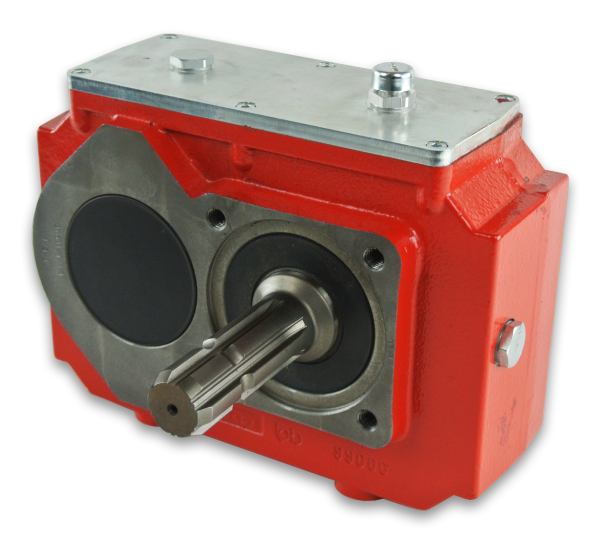
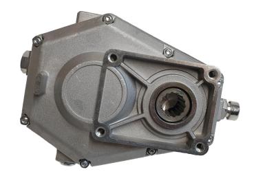
The Pump Drives (Hydraulic pump Drives) is a gearbox allowing the connection between a prime mover (internal combustion engine or electric motor for example) and 1 or more hydraulic pumps. Usually it is used on both stationary and mobile application where mechanical power must be converted into hydraulic power for the purpose of operating travel functions and services.
The hydraulic pumps drives gearboxes consist of a gear drive inside a CZPT housing that connects to a gasoline or diesel engine. The opposite side contains 1 or more standard 2- or 4-bolt flanges for mounting hydraulic pumps. This configuration provides several benefits. For one, 2 or more identical pumps can be connected to provide nearly identical hydraulic output flow from each. Or different sized pumps can be used provide output flow proportional to the displacement of each pump.These gearboxes not only saves space and weight but also eliminates the number of components and reduces assembly time for the whole machinery. Our modular pump drives could allow driving 2 to 4 pumps simultaneously. This not only offers design flexibility, but can boost system efficiency as well.
| Model | 2 pumps drive | 3 pumps drive | 4 pumps drive | |||||||
| Parameter | KK190-2N | KK400-2N | KK530-2N | KK700-2N | KK280-3N | KK400-3N | KK530-3N | KK700-3N | KK530-4N | KK700-4N |
| Max. Input power (KW) | 190 | 400 | 530 | 700 | 280 | 400 | 530 | 700 | 530 | 700 |
| Max. Output power per pump pad (KW) | 110 | 210 | 270 | 360 | 150 | 210 | 270 | 360 | 270 | 330 |
| Max. Output torque per pump pad (Nm) | 400 | 900 | 1500 | 1900 | 800 | 900 | 1500 | 1900 | 1500 | 1800 |
| Max. Input speed (RPM) | 2800 | 2600 | 2600 | 2400 | 2800 | 2600 | 2600 | 2400 | 2600 | 2400 |
| Max. Output speed (RPM) | 3200 | 2800 | 2800 | 2700 | 3200 | 2800 | 2800 | 2700 | 2800 | 2700 |
| Transmission ratio | 0.74/0.81/0.89/0.98··· | 0.67/0.74/0.81/0.89/0.98··· | 0.67/0.74/0.81/0.89/0.98··· | 0.67/0.74/0.81/0.89/0.98··· | 0.74/0.81/0.89/0.98··· | 0.67/0.74/0.81/0.89/0.98··· | 0.67/0.74/0.81/0.89/0.98··· | 0.67/0.74/0.81/0.89/0.98··· | 0.67/0.74/0.81/0.89/0.98··· | 0.67/0.74/0.81/0.89/0.98··· |
| Mount size of Prime mover | SAE #3 #4 etc. | SAE #2 #3 etc. | SAE #1 #2 #3 etc. | SAE #0 #1 #2 etc. | SAE #3 #4 etc. | SAE #2 #3 etc. | SAE #1 #2 #3 etc. | SAE #0 #1 #2 etc. | SAE #1 #2 #3 etc. | SAE #1 #2 etc. |
| Port size of Single pump | SAE A,B,C flange etc. | SAE A,B,C,D flange etc. | SAE B,C,D,E flange etc. | SAE C,D,E flange etc. | SAE A,B,C flange etc. | SAE A,B,C,D flange etc. | SAE B,C,D,E flange etc. | SAE C,D,E flange etc. | SAE B,C,D,E flange etc. | SAE B C,D flange etc. |
| ハウジング材 | Cast iron | Cast iron | Cast iron | Cast iron | Cast iron | Cast iron | Cast iron | Cast iron | Cast iron | Cast iron |
| 応用: | Machinery, Agricultural Machinery |
|---|---|
| 関数: | Distribution Power, Speed Changing, Speed Reduction, Speed Increase |
| インストール: | 横型 |
| Type: | Cylindrical Gear Box |
| Output Power Kw: | 110-330 |
| Housing Material: | Cast Iron |
| サンプル: |
US$ 4990/Piece
1個(最小注文数) | |
|---|
| Customization: |
Available
| Customized Request |
|---|
マイターギアボックスの使用における課題
マイターギアボックスには様々な利点がある一方で、対処すべき課題もいくつか存在する。
潤滑: マイターギアボックスでは、ギア歯間の摩擦、発熱、摩耗を最小限に抑えるために、適切な潤滑が不可欠です。ギアボックス内の潤滑を常に十分に保つことは、特に密閉された場所や手の届きにくい場所では困難な場合があります。
メンテナンス: マイターギアボックスは、最適な性能と長寿命を確保するために定期的なメンテナンスが必要です。メンテナンス作業には、潤滑油の点検と補充、ギア歯の摩耗検査、経年劣化により発生する可能性のある位置ずれや取り付け不良の対処などが含まれます。
反発: バックラッシュ、つまり歯車間の隙間は、動作伝達の精度に影響を与える可能性があります。バックラッシュが大きすぎると、高精度が求められる用途において、精度低下や位置決め誤差につながる可能性があります。
複雑な設計: マイターギアボックスは、他のタイプのギアボックスに比べて設計が複雑なため、製造、組み立て、メンテナンスがより難しくなる場合があります。この複雑さゆえに、製造コストとメンテナンスコストが高くなる可能性もあります。
効率損失: マイターギアボックスは、摩擦や芯ずれなどの要因により効率損失が発生する場合があります。これらの損失は動力伝達全体の効率を低下させ、エネルギーの無駄につながります。
スペースの制約: 用途によっては、特に所望の動作方向変更を実現するために大きなギア比が必要な場合、マイターギアボックスを組み込む際にスペースの制約が課題となることがあります。
衝撃荷重: 急激な衝撃荷重や高い衝撃力が加わる用途では、マイターギアボックスにとって課題となる場合があります。こうした課題に対処するためには、衝撃吸収部品の使用や耐久性を高める設計など、適切な対策が必要となる可能性があります。
位置合わせと取り付け: マイターギアボックスの適切な位置合わせと取り付けは、スムーズな動作を確保し、早期摩耗を防ぐために非常に重要です。特に、アクセスが制限された場所や複雑な形状の設置場所では、正確な位置合わせを実現するのは困難な場合があります。
費用に関する考慮事項: マイターギアボックスは、設計の複雑さや製造要件から、よりシンプルなタイプのギアボックスに比べてコストが高くなる場合があります。選定プロセスにおいては、マイターギアボックスの利点とそれに伴うコストのバランスを考慮することが不可欠です。
これらの課題に対処するには、綿密な設計、適切なメンテナンス、そして特定の用途要件への配慮が必要となる場合が多い。課題はあるものの、マイターギアボックスは、その独自の動作方向変更機能が有利となる様々な産業において、依然として重要な部品である。
Minimizing Backlash and Ensuring Accurate Motion Transfer in Miter Gearboxes
Miter gearboxes are meticulously designed to minimize backlash and ensure precise and accurate motion transfer between the input and output shafts. Backlash refers to the slight movement or play between the gear teeth when the direction of rotation is changed. Minimizing backlash is essential for maintaining positional accuracy, reducing vibration, and achieving smooth motion in mechanical systems.
Several design features and engineering considerations contribute to minimizing backlash in miter gearboxes:
- High-Quality Gearing: Miter gearboxes use high-quality bevel gears with precisely machined teeth and tight manufacturing tolerances. This ensures a snug fit between the gear teeth, reducing the potential for any free movement or play.
- Preload and Gear Mesh Arrangement: Engineers carefully calculate and implement gear preloading, which involves applying a slight force between the gear mesh. This eliminates any clearance between the gear teeth, effectively reducing backlash.
- Bearing Arrangement: Proper bearing selection and arrangement play a critical role in minimizing backlash. High-quality bearings with minimal axial play are chosen to support the gear shafts and maintain precise alignment.
- Housing and Casing Rigidity: The gearbox housing is designed to provide optimal rigidity and support to the internal components. This helps prevent deflection or deformation that could contribute to backlash.
- 潤滑: Adequate lubrication is essential to reduce friction and wear between the gear teeth. Proper lubrication helps maintain the gear mesh and minimizes any irregular movement.
By incorporating these design principles and techniques, miter gearboxes are able to achieve accurate motion transfer with minimal backlash. This is particularly important in applications where precision positioning, synchronization, and reliable motion control are critical, such as robotics, CNC machinery, and automation systems.
Miter Gearbox: Function and Mechanism
A miter gearbox, also known as a bevel gearbox or angle gearbox, is a type of gearbox that transmits power and changes the direction of rotational motion between intersecting shafts positioned at a 90-degree angle to each other. It consists of a set of bevel gears with intersecting axes.
The function of a miter gearbox in mechanical systems is to redirect the rotational motion of input shaft(s) to output shaft(s) at a right angle. This allows for power transmission and torque conversion between two shafts that are not aligned. Miter gearboxes are particularly useful when space constraints or specific mechanical configurations require a change in the direction of motion.
The working principle of a miter gearbox involves the meshing of bevel gears. Bevel gears have conically shaped teeth that enable them to mesh smoothly at a 90-degree angle. When the input shaft rotates, the teeth of the input bevel gear engage with the teeth of the output bevel gear, causing the output shaft to rotate perpendicularly to the input shaft. The gear ratio and number of teeth on the gears determine the speed and torque conversion between the input and output shafts.
Miter gearboxes find applications in various industries, such as automotive, machinery, agriculture, and robotics, where changes in motion direction are required. They are often used in equipment that needs to transmit power around corners or in tight spaces while maintaining the desired torque and speed characteristics.


editor by CX 2023-09-06