Product Description
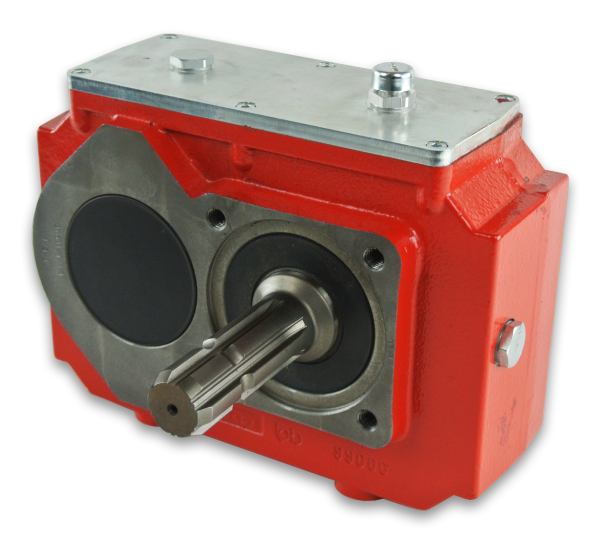
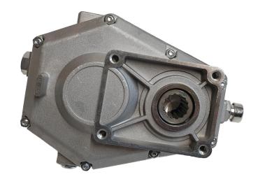
The Pump Drives (Hydraulic pump Drives) is a gearbox allowing the connection between a prime mover (internal combustion engine or electric motor for example) and 1 or more hydraulic pumps. Usually it is used on both stationary and mobile application where mechanical power must be converted into hydraulic power for the purpose of operating travel functions and services.
The hydraulic pumps drives gearboxes consist of a gear drive inside a CZPT housing that connects to a gasoline or diesel engine. The opposite side contains 1 or more standard 2- or 4-bolt flanges for mounting hydraulic pumps. This configuration provides several benefits. For one, 2 or more identical pumps can be connected to provide nearly identical hydraulic output flow from each. Or different sized pumps can be used provide output flow proportional to the displacement of each pump.These gearboxes not only saves space and weight but also eliminates the number of components and reduces assembly time for the whole machinery. Our modular pump drives could allow driving 2 to 4 pumps simultaneously. This not only offers design flexibility, but can boost system efficiency as well.
| Model | 2 pumps drive | 3 pumps drive | 4 pumps drive | |||||||
| Parameter | KK190-2N | KK400-2N | KK530-2N | KK700-2N | KK280-3N | KK400-3N | KK530-3N | KK700-3N | KK530-4N | KK700-4N |
| Max. Input power (KW) | 190 | 400 | 530 | 700 | 280 | 400 | 530 | 700 | 530 | 700 |
| Max. Output power per pump pad (KW) | 110 | 210 | 270 | 360 | 150 | 210 | 270 | 360 | 270 | 330 |
| Max. Output torque per pump pad (Nm) | 400 | 900 | 1500 | 1900 | 800 | 900 | 1500 | 1900 | 1500 | 1800 |
| Max. Input speed (RPM) | 2800 | 2600 | 2600 | 2400 | 2800 | 2600 | 2600 | 2400 | 2600 | 2400 |
| Max. Output speed (RPM) | 3200 | 2800 | 2800 | 2700 | 3200 | 2800 | 2800 | 2700 | 2800 | 2700 |
| Transmission ratio | 0.74/0.81/0.89/0.98··· | 0.67/0.74/0.81/0.89/0.98··· | 0.67/0.74/0.81/0.89/0.98··· | 0.67/0.74/0.81/0.89/0.98··· | 0.74/0.81/0.89/0.98··· | 0.67/0.74/0.81/0.89/0.98··· | 0.67/0.74/0.81/0.89/0.98··· | 0.67/0.74/0.81/0.89/0.98··· | 0.67/0.74/0.81/0.89/0.98··· | 0.67/0.74/0.81/0.89/0.98··· |
| Mount size of Prime mover | SAE #3 #4 etc. | SAE #2 #3 etc. | SAE #1 #2 #3 etc. | SAE #0 #1 #2 etc. | SAE #3 #4 etc. | SAE #2 #3 etc. | SAE #1 #2 #3 etc. | SAE #0 #1 #2 etc. | SAE #1 #2 #3 etc. | SAE #1 #2 etc. |
| Port size of Single pump | SAE A,B,C flange etc. | SAE A,B,C,D flange etc. | SAE B,C,D,E flange etc. | SAE C,D,E flange etc. | SAE A,B,C flange etc. | SAE A,B,C,D flange etc. | SAE B,C,D,E flange etc. | SAE C,D,E flange etc. | SAE B,C,D,E flange etc. | SAE B C,D flange etc. |
| Housing material | Cast iron | Cast iron | Cast iron | Cast iron | Cast iron | Cast iron | Cast iron | Cast iron | Cast iron | Cast iron |
| Application: | Machinery, Agricultural Machinery |
|---|---|
| Function: | Distribution Power, Speed Changing, Speed Reduction, Speed Increase |
| Installation: | Horizontal Type |
| Type: | Cylindrical Gear Box |
| Output Power Kw: | 110-330 |
| Housing Material: | Cast Iron |
| Samples: |
US$ 4990/Piece
1 Piece(Min.Order) | |
|---|
| Customization: |
Available
| Customized Request |
|---|
Challenges in Using Miter Gearboxes
While miter gearboxes offer various advantages, they also come with certain challenges that need to be addressed:
Lubrication: Proper lubrication is crucial for miter gearboxes to minimize friction, heat, and wear between gear teeth. Ensuring consistent and sufficient lubrication in the gearbox can be challenging, especially in enclosed or hard-to-reach spaces.
Maintenance: Miter gearboxes require periodic maintenance to ensure their optimal performance and longevity. Maintenance tasks may include checking and replenishing lubrication, inspecting gear teeth for wear, and addressing any misalignment or mounting issues that may arise over time.
Backlash: Backlash, or the clearance between gear teeth, can impact the accuracy of motion transfer. Excessive backlash can lead to reduced precision and positioning errors in applications that require high accuracy.
Complex Design: Miter gearboxes have a more intricate design compared to some other gearbox types, which can make manufacturing, assembly, and maintenance more complex. This complexity may also result in higher manufacturing and maintenance costs.
Efficiency Loss: Miter gearboxes can experience efficiency losses due to factors such as friction and misalignment. These losses can reduce the overall efficiency of power transmission, leading to energy wastage.
Space Constraints: In some applications, space limitations can pose a challenge when integrating miter gearboxes, especially when larger gear ratios are required to achieve the desired motion direction change.
Shock Loads: Applications subject to sudden shock loads or high impact forces can pose challenges for miter gearboxes. Adequate measures, such as using shock-absorbing components or designing for higher durability, may be required to address these challenges.
Alignment and Mounting: Proper alignment and mounting of miter gearboxes are critical to ensure smooth operation and prevent premature wear. Achieving precise alignment can be challenging, especially in installations with limited access or complex geometries.
Cost Considerations: The design complexity and manufacturing requirements of miter gearboxes can contribute to higher costs compared to simpler gearbox types. Balancing the benefits of miter gearboxes with the associated costs is essential during the selection process.
Addressing these challenges often requires careful engineering, proper maintenance practices, and consideration of specific application requirements. Despite the challenges, miter gearboxes remain valuable components in various industries where their unique motion direction-changing capabilities are advantageous.
Minimizing Backlash and Ensuring Accurate Motion Transfer in Miter Gearboxes
Miter gearboxes are meticulously designed to minimize backlash and ensure precise and accurate motion transfer between the input and output shafts. Backlash refers to the slight movement or play between the gear teeth when the direction of rotation is changed. Minimizing backlash is essential for maintaining positional accuracy, reducing vibration, and achieving smooth motion in mechanical systems.
Several design features and engineering considerations contribute to minimizing backlash in miter gearboxes:
- High-Quality Gearing: Miter gearboxes use high-quality bevel gears with precisely machined teeth and tight manufacturing tolerances. This ensures a snug fit between the gear teeth, reducing the potential for any free movement or play.
- Preload and Gear Mesh Arrangement: Engineers carefully calculate and implement gear preloading, which involves applying a slight force between the gear mesh. This eliminates any clearance between the gear teeth, effectively reducing backlash.
- Bearing Arrangement: Proper bearing selection and arrangement play a critical role in minimizing backlash. High-quality bearings with minimal axial play are chosen to support the gear shafts and maintain precise alignment.
- Housing and Casing Rigidity: The gearbox housing is designed to provide optimal rigidity and support to the internal components. This helps prevent deflection or deformation that could contribute to backlash.
- Lubrication: Adequate lubrication is essential to reduce friction and wear between the gear teeth. Proper lubrication helps maintain the gear mesh and minimizes any irregular movement.
By incorporating these design principles and techniques, miter gearboxes are able to achieve accurate motion transfer with minimal backlash. This is particularly important in applications where precision positioning, synchronization, and reliable motion control are critical, such as robotics, CNC machinery, and automation systems.
Miter Gearbox: Function and Mechanism
A miter gearbox, also known as a bevel gearbox or angle gearbox, is a type of gearbox that transmits power and changes the direction of rotational motion between intersecting shafts positioned at a 90-degree angle to each other. It consists of a set of bevel gears with intersecting axes.
The function of a miter gearbox in mechanical systems is to redirect the rotational motion of input shaft(s) to output shaft(s) at a right angle. This allows for power transmission and torque conversion between two shafts that are not aligned. Miter gearboxes are particularly useful when space constraints or specific mechanical configurations require a change in the direction of motion.
The working principle of a miter gearbox involves the meshing of bevel gears. Bevel gears have conically shaped teeth that enable them to mesh smoothly at a 90-degree angle. When the input shaft rotates, the teeth of the input bevel gear engage with the teeth of the output bevel gear, causing the output shaft to rotate perpendicularly to the input shaft. The gear ratio and number of teeth on the gears determine the speed and torque conversion between the input and output shafts.
Miter gearboxes find applications in various industries, such as automotive, machinery, agriculture, and robotics, where changes in motion direction are required. They are often used in equipment that needs to transmit power around corners or in tight spaces while maintaining the desired torque and speed characteristics.


editor by CX 2023-09-06