وصف المنتج
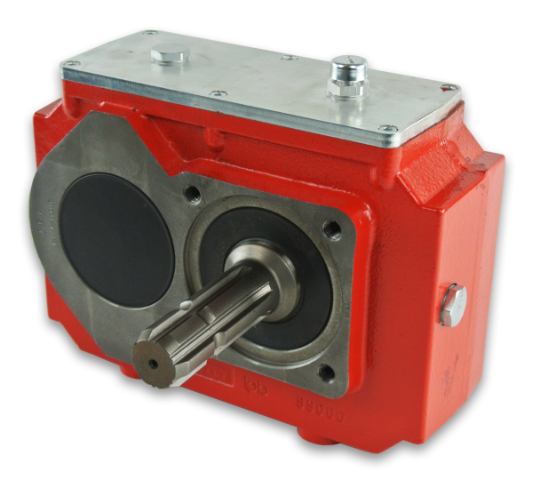
The Pump Drives (Hydraulic pump Drives) is a gearbox allowing the connection between a prime mover (internal combustion engine or electric motor for example) and 1 or more hydraulic pumps. Usually it is used on both stationary and mobile application where mechanical power must be converted into hydraulic power for the purpose of operating travel functions and services.
The hydraulic pumps drives gearboxes consist of a gear drive inside a CZPT housing that connects to a gasoline or diesel engine. The opposite side contains 1 or more standard 2- or 4-bolt flanges for mounting hydraulic pumps. This configuration provides several benefits. For one, 2 or more identical pumps can be connected to provide nearly identical hydraulic output flow from each. Or different sized pumps can be used provide output flow proportional to the displacement of each pump.These gearboxes not only saves space and weight but also eliminates the number of components and reduces assembly time for the whole machinery. Our modular pump drives could allow driving 2 to 4 pumps simultaneously. This not only offers design flexibility, but can boost system efficiency as well.
| نموذج | 2 pumps drive | 3 pumps drive | 4 pumps drive | |||||||
| المعلمة | KK190-2N | KK400-2N | KK530-2N | KK700-2N | KK280-3N | KK400-3N | KK530-3N | KK700-3N | KK530-4N | KK700-4N |
| Max. Input power (KW) | 190 | 400 | 530 | 700 | 280 | 400 | 530 | 700 | 530 | 700 |
| Max. Output power per pump pad (KW) | 110 | 210 | 270 | 360 | 150 | 210 | 270 | 360 | 270 | 330 |
| Max. Output torque per pump pad (Nm) | 400 | 900 | 1500 | 1900 | 800 | 900 | 1500 | 1900 | 1500 | 1800 |
| Max. Input speed (RPM) | 2800 | 2600 | 2600 | 2400 | 2800 | 2600 | 2600 | 2400 | 2600 | 2400 |
| Max. Output speed (RPM) | 3200 | 2800 | 2800 | 2700 | 3200 | 2800 | 2800 | 2700 | 2800 | 2700 |
| Transmission ratio | 0.74/0.81/0.89/0.98··· | 0.67/0.74/0.81/0.89/0.98··· | 0.67/0.74/0.81/0.89/0.98··· | 0.67/0.74/0.81/0.89/0.98··· | 0.74/0.81/0.89/0.98··· | 0.67/0.74/0.81/0.89/0.98··· | 0.67/0.74/0.81/0.89/0.98··· | 0.67/0.74/0.81/0.89/0.98··· | 0.67/0.74/0.81/0.89/0.98··· | 0.67/0.74/0.81/0.89/0.98··· |
| Mount size of Prime mover | SAE #3 #4 etc. | SAE #2 #3 etc. | SAE #1 #2 #3 etc. | SAE #0 #1 #2 etc. | SAE #3 #4 etc. | SAE #2 #3 etc. | SAE #1 #2 #3 etc. | SAE #0 #1 #2 etc. | SAE #1 #2 #3 etc. | SAE #1 #2 etc. |
| Port size of Single pump | SAE A,B,C flange etc. | SAE A,B,C,D flange etc. | SAE B,C,D,E flange etc. | SAE C,D,E flange etc. | SAE A,B,C flange etc. | SAE A,B,C,D flange etc. | SAE B,C,D,E flange etc. | SAE C,D,E flange etc. | SAE B,C,D,E flange etc. | SAE B C,D flange etc. |
| Housing material | Cast iron | Cast iron | Cast iron | Cast iron | Cast iron | Cast iron | Cast iron | Cast iron | Cast iron | Cast iron |
| طلب: | Machinery, Agricultural Machinery |
|---|---|
| وظيفة: | Distribution Power, Speed Changing, Speed Reduction, Speed Increase |
| تثبيت: | النوع الأفقي |
| يكتب: | Cylindrical Gear Box |
| Output Power Kw: | 110-330 |
| Housing Material: | حديد الزهر |
| أمثلة: |
US$ 4990/Piece
قطعة واحدة (الحد الأدنى للطلب) | |
|---|
| التخصيص: |
متاح
| طلب مخصص |
|---|
تحديات استخدام علب التروس المائلة
على الرغم من أن علب التروس المائلة توفر مزايا عديدة، إلا أنها تأتي أيضاً مع تحديات معينة يجب معالجتها:
تشحيم: يُعدّ التشحيم السليم أمراً بالغ الأهمية لعلب تروس التروس المائلة لتقليل الاحتكاك والحرارة والتآكل بين أسنان التروس. وقد يكون ضمان التشحيم المنتظم والكافي داخل علبة التروس أمراً صعباً، لا سيما في الأماكن المغلقة أو التي يصعب الوصول إليها.
صيانة: تتطلب علب التروس المائلة صيانة دورية لضمان أدائها الأمثل وعمرها الطويل. قد تشمل مهام الصيانة فحص وتجديد مواد التشحيم، وفحص أسنان التروس للتأكد من عدم تآكلها، ومعالجة أي مشاكل في المحاذاة أو التركيب قد تظهر مع مرور الوقت.
ردود الفعل العنيفة: يمكن أن يؤثر الخلوص، أو المسافة بين أسنان التروس، على دقة نقل الحركة. وقد يؤدي الخلوص المفرط إلى انخفاض الدقة وظهور أخطاء في تحديد المواقع في التطبيقات التي تتطلب دقة عالية.
التصميم المعقد: تتميز علب التروس المخروطية بتصميم أكثر تعقيدًا مقارنةً ببعض أنواع علب التروس الأخرى، مما قد يزيد من تعقيد عمليات التصنيع والتجميع والصيانة. وقد يؤدي هذا التعقيد أيضًا إلى ارتفاع تكاليف التصنيع والصيانة.
خسارة الكفاءة: قد تتعرض علب التروس المخروطية لانخفاض في الكفاءة نتيجة عوامل مثل الاحتكاك وعدم المحاذاة. ويمكن أن يؤدي هذا الانخفاض إلى تقليل الكفاءة الإجمالية لنقل الطاقة، مما ينتج عنه هدر للطاقة.
قيود المساحة: في بعض التطبيقات، يمكن أن تشكل قيود المساحة تحديًا عند دمج علب التروس المائلة، خاصة عندما تكون هناك حاجة إلى نسب تروس أكبر لتحقيق تغيير اتجاه الحركة المطلوب.
أحمال الصدمات: قد تُشكّل التطبيقات التي تتعرض لأحمال صدمات مفاجئة أو قوى ارتطام عالية تحدياتٍ لصناديق التروس المائلة. وقد يتطلب الأمر اتخاذ تدابير مناسبة، مثل استخدام مكونات ماصة للصدمات أو تصميمها لزيادة متانتها، للتغلب على هذه التحديات.
المحاذاة والتركيب: يُعدّ ضبط وتركيب علب تروس التوجيه المائلة بشكل صحيح أمرًا بالغ الأهمية لضمان التشغيل السلس ومنع التآكل المبكر. وقد يكون تحقيق الضبط الدقيق أمرًا صعبًا، لا سيما في التركيبات ذات الوصول المحدود أو الأشكال الهندسية المعقدة.
اعتبارات التكلفة: قد تُسهم تعقيدات تصميم وتصنيع علب التروس المائلة في ارتفاع التكاليف مقارنةً بأنواع علب التروس الأبسط. لذا، يُعدّ تحقيق التوازن بين مزايا علب التروس المائلة والتكاليف المرتبطة بها أمرًا بالغ الأهمية خلال عملية الاختيار.
غالباً ما يتطلب التغلب على هذه التحديات هندسة دقيقة، وممارسات صيانة سليمة، ومراعاة متطلبات التطبيق المحددة. وعلى الرغم من هذه التحديات، تظل علب التروس المائلة مكونات قيّمة في مختلف الصناعات حيث تُعدّ قدراتها الفريدة على تغيير اتجاه الحركة ميزةً قيّمة.
Minimizing Backlash and Ensuring Accurate Motion Transfer in Miter Gearboxes
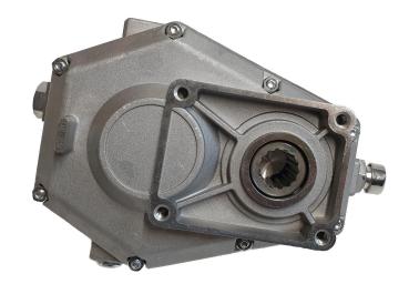
Miter gearboxes are meticulously designed to minimize backlash and ensure precise and accurate motion transfer between the input and output shafts. Backlash refers to the slight movement or play between the gear teeth when the direction of rotation is changed. Minimizing backlash is essential for maintaining positional accuracy, reducing vibration, and achieving smooth motion in mechanical systems.
Several design features and engineering considerations contribute to minimizing backlash in miter gearboxes:
- High-Quality Gearing: Miter gearboxes use high-quality bevel gears with precisely machined teeth and tight manufacturing tolerances. This ensures a snug fit between the gear teeth, reducing the potential for any free movement or play.
- Preload and Gear Mesh Arrangement: Engineers carefully calculate and implement gear preloading, which involves applying a slight force between the gear mesh. This eliminates any clearance between the gear teeth, effectively reducing backlash.
- Bearing Arrangement: Proper bearing selection and arrangement play a critical role in minimizing backlash. High-quality bearings with minimal axial play are chosen to support the gear shafts and maintain precise alignment.
- Housing and Casing Rigidity: The gearbox housing is designed to provide optimal rigidity and support to the internal components. This helps prevent deflection or deformation that could contribute to backlash.
- تشحيم: Adequate lubrication is essential to reduce friction and wear between the gear teeth. Proper lubrication helps maintain the gear mesh and minimizes any irregular movement.
By incorporating these design principles and techniques, miter gearboxes are able to achieve accurate motion transfer with minimal backlash. This is particularly important in applications where precision positioning, synchronization, and reliable motion control are critical, such as robotics, CNC machinery, and automation systems.
Miter Gearbox: Function and Mechanism
A miter gearbox, also known as a bevel gearbox or angle gearbox, is a type of gearbox that transmits power and changes the direction of rotational motion between intersecting shafts positioned at a 90-degree angle to each other. It consists of a set of bevel gears with intersecting axes.
The function of a miter gearbox in mechanical systems is to redirect the rotational motion of input shaft(s) to output shaft(s) at a right angle. This allows for power transmission and torque conversion between two shafts that are not aligned. Miter gearboxes are particularly useful when space constraints or specific mechanical configurations require a change in the direction of motion.
The working principle of a miter gearbox involves the meshing of bevel gears. Bevel gears have conically shaped teeth that enable them to mesh smoothly at a 90-degree angle. When the input shaft rotates, the teeth of the input bevel gear engage with the teeth of the output bevel gear, causing the output shaft to rotate perpendicularly to the input shaft. The gear ratio and number of teeth on the gears determine the speed and torque conversion between the input and output shafts.
Miter gearboxes find applications in various industries, such as automotive, machinery, agriculture, and robotics, where changes in motion direction are required. They are often used in equipment that needs to transmit power around corners or in tight spaces while maintaining the desired torque and speed characteristics.


editor by CX 2023-09-06