
Produktbeschreibung
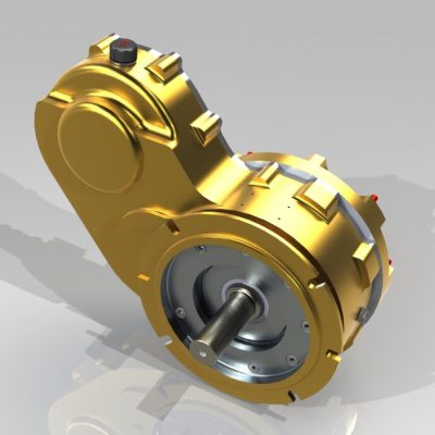
Tractor PTO double gearbox driven flail lawn mower (AG200)
Uses:
The AG series flail mower is a super heavy duty flail mower designed for large areas, roadside verges, orchards and general farm areas. Dual-mount for using at front or rear of tractors. Hydraulic side-shift. Perfect for maintaining more rugged landscape areas including heavy grasses, storm debris, sticks, vines and more areas around farms, properties, parklands and roadsides.
Merkmale:
Dual mountable because of the double head gearbox
Suited for tractors with front and or rear PTO and hydraulic remotes
Hydraulic side shift allows the AG flail mowers to cut close to farm boundaries, around obstructions and trees as well as roadsides
AG flail mower is fitted with a high power 50hp gearbox
Cutting height contolled by adjustable skids
High strength mulching blades
Specifications:
Model: AG170
Net Weight: 437KG
Gross Weight: 499KG
Working Width: 1680mm
PTO Turning Speed: 540r/min
Flail Type: Hammer
Number Of Flails: 14
Tractor HP: 40-50hp
Why choose CHINAMFG IMPLEMENT:
Any quality problem you have in 1 year, we promise to help you solve asap.
Every customer to us is unique, best service will give you.
We provide you our machine with good material and promise not to deduct the material.
Every model of our machine will have a testing before the delivery to the port.
If you want to visit our factory, our boss will give you a best reception.
Every year’s Christmas we prepare gifts to our customer.
Every year we attend the agricultural exhibition in Germany or Italy.
Shipment
Werkstatt
Certificate
| Typ: | Professional Mowers |
|---|---|
| Moving Way: | Tractor-Mounted |
| Applicable Area: | 500-1000m² |
| Feature: | 2-Stroke, Steel Chassis, Mulch |
| Certification: | CE |
| Cutter Kind: | Hammer |
| Anpassung: |
Verfügbar
| Kundenspezifische Anfrage |
|---|
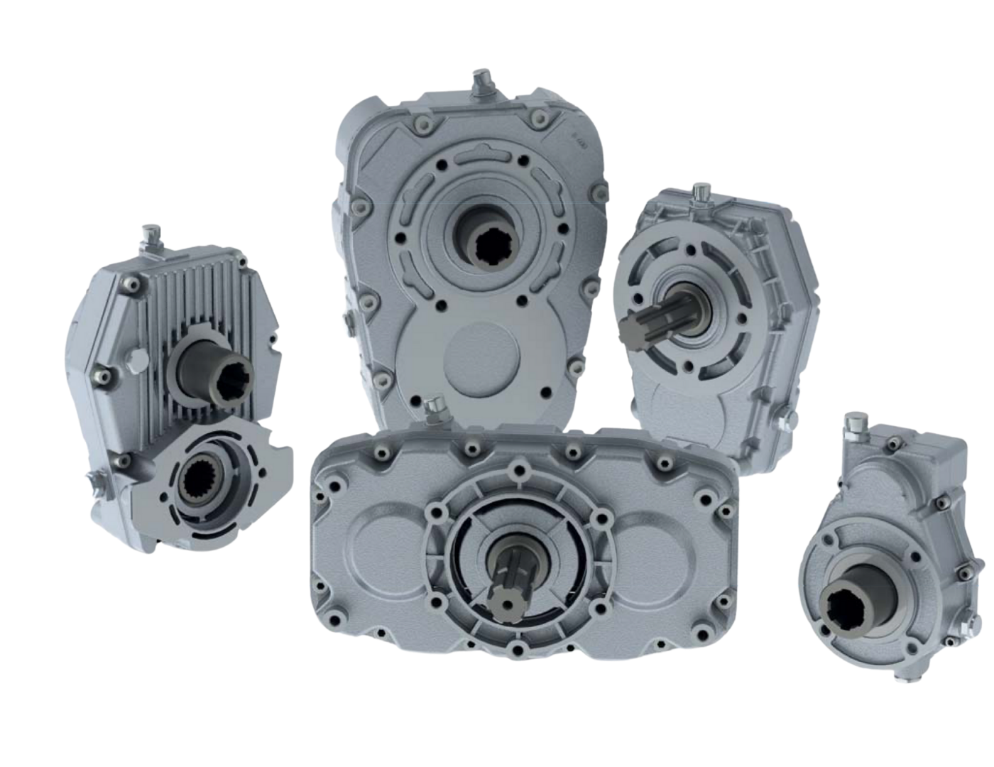
Proper Installation and Alignment of Miter Gearboxes
Installing and aligning a miter gearbox correctly is essential to ensure its optimal performance and longevity. Follow these steps to achieve proper installation and alignment:
- Preparation: Gather all necessary tools and equipment for the installation, including mounting hardware, shims, and alignment tools.
- Mounting Surface: Ensure that the mounting surface is clean, flat, and free from any debris or contaminants that could affect the gearbox’s alignment and operation.
- Alignment Tools: Use precision alignment tools, such as dial indicators or laser alignment systems, to accurately measure and adjust the alignment of the gearbox and its input and output shafts.
- Check for Parallelism: Align the input and output shafts of the gearbox to be parallel to each other and perpendicular to the mounting surface. This step is crucial to prevent misalignment-induced wear and reduce backlash.
- Adjustment: Use shims or other adjustable components to fine-tune the alignment. Make incremental adjustments while continuously checking the alignment with the chosen alignment tools.
- Bearing Loads: Ensure that the bearings supporting the gearbox shafts are properly lubricated and preloaded according to the manufacturer’s recommendations. Proper bearing preload helps maintain alignment and reduces wear.
- Tightening Bolts: Tighten the mounting bolts gradually and evenly to avoid introducing additional misalignment during the installation process.
- Runout and Clearance: Check for any runout or clearance issues during rotation by turning the input shaft. If there is any binding, interference, or abnormal noise, investigate and address the cause before finalizing the installation.
- Final Checks: Double-check the alignment using the alignment tools and ensure that the gearbox operates smoothly without any unusual vibrations, noises, or resistance.
- Documentation: Keep a record of the alignment measurements and adjustments made during the installation process. This documentation can be valuable for future reference and maintenance.
Proper installation and alignment of miter gearboxes help optimize their performance, minimize wear and tear, and contribute to the overall efficiency and reliability of the mechanical system in which they are used.
Miter Gearboxes in Robotics and Automation Applications
Miter gearboxes are indeed utilized in robotics and automation applications, leveraging their unique capabilities for precise motion control and direction change:
Precision Motion: In robotics, miter gearboxes can be employed to achieve precise and accurate motion at right angles, allowing robots to perform intricate tasks with accuracy.
Joint and Arm Movements: Robotic arms often require precise movement and control at various angles. Miter gearboxes enable smooth and controlled motion changes, contributing to the versatility of robotic arms.
Direction Change: Many automation systems involve the need to change the direction of motion, such as conveyors or assembly lines. Miter gearboxes efficiently handle these changes, ensuring seamless operation.
Space Optimization: Robots and automated systems often operate in confined spaces. Miter gearboxes’ compact design makes them suitable for integrating into space-constrained environments.
Responsive Control: Automation applications demand responsiveness and accurate control. Miter gearboxes provide the necessary motion control for timely and precise execution of tasks.
Noise Reduction: In robotics and automation, quiet operation is essential. Miter gearboxes, with reduced backlash and noise, contribute to a quieter working environment.
Miter gearboxes play a crucial role in enhancing the efficiency, accuracy, and versatility of robotics and automation systems by facilitating controlled motion changes and direction shifts.
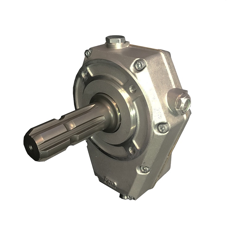
Änderung der Drehrichtung mit Winkelgetrieben
Winkelgetriebe sind spezielle mechanische Geräte, die die Drehrichtung effizient um 90 Grad ändern. Sie erreichen diese Richtungsänderung durch den Einsatz von Kegelrädern mit sich kreuzenden Wellen:
- Kegelräder: Kegelradgetriebe verwenden Kegelräder mit kegelförmigen Zähnen. Diese Zahnräder sind schräg zur Zahnstirnfläche gezahnt und ermöglichen die Kraftübertragung zwischen zwei sich kreuzenden Wellen, die in einem 90-Grad-Winkel zueinander angeordnet sind.
- Sich kreuzende Schächte: Die Eingangs- und Ausgangswelle eines Kegelradgetriebes sind so angeordnet, dass sie sich rechtwinklig schneiden. Die Kegelräder sind auf diesen Wellen montiert. Dreht sich die Eingangswelle, greift sie in die Zähne des Kegelrads auf der Ausgangswelle ein und überträgt so die Bewegung im rechten Winkel.
- Richtungsänderung: Während sich die Eingangswelle dreht, greifen die Zähne des Kegelrads ineinander und übertragen die Bewegung von der Eingangswelle auf die Ausgangswelle. Diese Wechselwirkung bewirkt eine Änderung der Drehrichtung, wodurch die Ausgangsbewegung senkrecht zur Eingangsbewegung ausgerichtet wird.
- Kompaktes Design: Winkelgetriebe zeichnen sich durch ihre kompakte und platzsparende Bauweise aus. Die sich kreuzenden Wellen und Kegelräder sind im Getriebegehäuse untergebracht, was eine effiziente Bewegungsumleitung ohne zusätzliche externe Bauteile ermöglicht.
Insgesamt spielen Winkelgetriebe eine entscheidende Rolle bei der Änderung der Drehrichtung und sind daher unverzichtbare Komponenten in verschiedenen mechanischen Systemen, in denen die Bewegung effizient und präzise umgelenkt werden muss.


editor by CX 2023-12-04


